
Programmable Machines can be as simple as a one note music box – or as complex as a modern billions-of-transistors microprocessor. This lesson builds on the concept of a single bit (2 instruction) “computer” by extending the instruction set and functionality to eventually show a simple but powerful 3-bit (8 instruction) graphics computer. This simple machine is capable of drawing virtually any image … with enough programming. Let’s get started.
This animation shows the progression of “computers” from the first single bit mechanical “computer” all the way through to a 3-bit graphics computer capable of drawing any image. These simple computers will be described individually below.

Simple 1-bit (2 instruction) Mechanical Computer

This “computer” consists of an electric motor turning a “programmable” wheel that turns a light on and off. The programmable “instructions” are simply a series of washers that are screwed onto the wheel. When a washer is present, the light switch is pressed and the light is turned on. When a washer is missing, the light switch turns the light off.
This is about the simplest programmable computer possible. The “instructions” are either “on” or “off”, and the “program” is just the series of “on” and “off” values that control the light.
Simple 1-bit (2 instruction) Electronic Computer

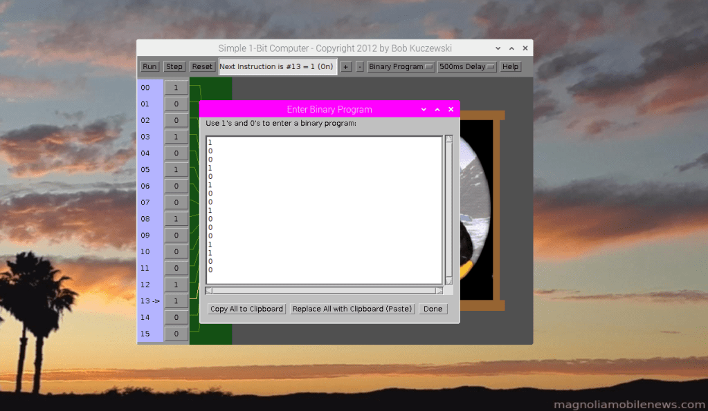
This one-bit computer is simply an electronic version of the previous mechanical computer. Each one-bit instruction is just an “on” or “off” represented by “1” and “0”. Rather than pushing a mechanical switch, these 1’s and 0’s enable a power transistor that sends current through the light. It is logically similar to the mechanical version, but it has a variable number of instructions, and it can be run at much faster speeds. Since each “instruction” is a “1” or a “0”, there’s very little advantage to using names (like “on” or “off”) since these names would take more typing to write a program than using the raw binary values of “1” and “0”. So this simple machine is only programmed in binary. The following picture shows a binary program being coded into the machine. The 1’s and 0’s of the program match the 1’s and 0’s of the programmable switches (instructions).
Simple 3-bit (8 instruction) Computer

This simple 3-bit computer is really just three separate 1-bit computers where each 1-bit computer is connected to a different colored light (red, green, and blue). The instruction stepping of the three separate 1-bit computers are effectively locked together so that they operate synchronously. The binary instructions range from 000 through 111. The 000 instruction means that all three lights (red, green, and blue) are turned off which gives the color black. Similarly, if all three lights (red, green, and blue) are turned on, they combine to give the color white. Other combinations generate other colors. The full set of instructions and resulting color combinations are:
| Instruction | Red | Green | Blue | Color | Code |
| 000 | 0 | 0 | 0 | Black | k |
| 100 | 1 | 0 | 0 | Red | r |
| 010 | 0 | 1 | 0 | Green | g |
| 001 | 0 | 0 | 1 | Blue | b |
| 110 | 1 | 1 | 0 | Yellow | y |
| 101 | 1 | 0 | 1 | Magenta | m |
| 011 | 0 | 1 | 1 | Cyan | c |
| 111 | 1 | 1 | 1 | White | w |
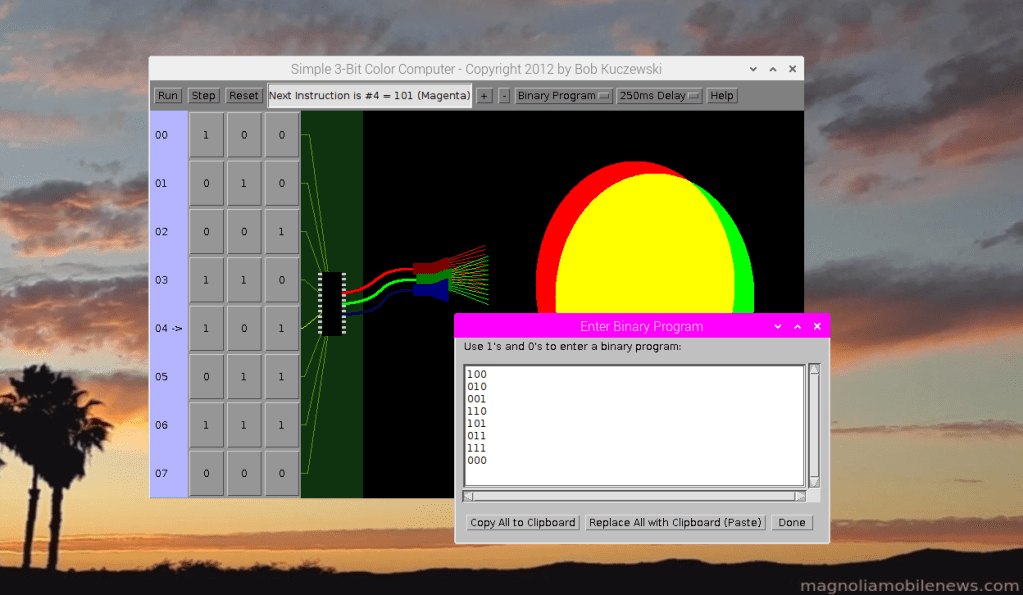
The following image shows both the “physical” program (switch settings) and the binary computer program in the editing window. This program steps through the colors in the sequence of red, green, blue, yellow, magenta, cyan, and black.
Note that the last column of the earlier table shows a single character “code” for each color. These “codes” are used to make it easier for people (humans) to write programs for this machine. These “codes” can be translated to the 1’s and 0’s that the machine understands. The “Help” button shows the correspondence between binary switch settings (binary instructions), operation codes (“Op Codes”), and the color names for each instruction:

In other words, this “computer” can be programmed in “binary” (1’s and 0’s), but it can also be programmed with the codes (r, g, b, y, m, c, w, k). Note that because blue and black both start with “b”, they couldn’t both use the same op code letter. So the computer “language” writer for this machine chose to use “k” for black. This points out that the instruction names for any machine instruction can be arbitrary as long as the translation is unambiguous. The following picture shows the same program “coded” with one-letter op codes rather than the 1’s and 0’s used earlier. In the software development world, this would be called “assembly language”. The one’s and zero’s version would be called “machine language”.

Simple 2-bit (4 instruction) Graphics Computer

This 2-bit graphics computer allows drawing of any connected figure very similar to the familiar “Etch-A-Sketch” toy. As with the “Etch-A-Sketch, the “pen” can never leave the “paper” in this computer. There are only four instructions: Up, Down, Right, and Left.
These 4 instructions are encoded as follows:
| Instruction | Machine Code | Op Code |
| Down | 00 | D |
| Right | 01 | R |
| Left | 10 | L |
| Up | 11 | U |
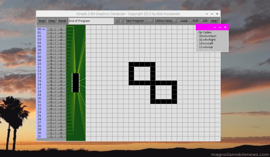
Note that the machine codes were assigned their values to be hopefully memorable to human programmers. For example, if the “1” is on the right (as in “01”), then that instruction means “Right”. If the “1” is on the left (as in “10”), then that instruction means “Left”. The “00” was chosen as “Down” because it’s the lowest value of the 4, and “11” was chosen as “Up” because it’s the highest value of the 4. But as with the 3-bit color computer, it’s much easier to remember the single letter op codes (U,D,R,L) than to remember the binary machine code values (11, 00, 01, 10) for each instruction. The following image shows the “assembly language” program to draw the lazy 8 figure. The program first goes “Left” with a series of 4 “L” codes. Then it goes “Up” with 4 “U” codes. It then goes “Right” with 4 “R” codes. It goes “Down” with 8 “D” codes, followed by “Right” with 4 “R” codes, “Up” again with four “U” codes, and finally “Left” with 4 “L” codes to bring it back where it started:

Simple 3-bit 2-color Graphics Computer

This 3-bit computer is identical to the 2-bit version, except that it has an extra bit to determine whether the “pen” is up or down when moving. So the same 4 instructions in the earlier machine (D,R,L,U), are essentially repeated twice – once with the pen up (0xx) and once with the pen down (1xx). This allows “Move” commands (prefixed with an “M”) and “Draw” commands (prefixed with a “D”). The following table defines all possible instructions:
| Instruction | Machine Code | Op Code |
| Move Down | 000 | MD |
| Move Right | 001 | MR |
| Move Left | 010 | ML |
| Move Up | 011 | MU |
| Draw Down | 100 | DD |
| Draw Right | 101 | DR |
| Draw Left | 110 | DL |
| Draw Up | 111 | DU |
As mentioned earlier, the Op Codes are designed to be “relatively” easy for a human programmer to remember. And while a person could write a program in either binary (all 1’s and 0’s) or “assembly” (op codes), the assembly language is much easier to both write … and to read. The following image shows the “smiley face” program after running on this machine. The instruction set (op codes) are shown in the upper right window, and a portion of the “program” itself is shown in the text editor window.

This machine has the ability to draw virtually any black and white image. It could even use “dithering” to represent shades of gray.
Simple 3-bit Full Color Graphics Computer

This is also a 3-bit computer, but it uses “immediate data” values to specify a wide range of colors. The use of immediate values is a small trade-off in speed to keep the instructions themselves small (still only 3 bits). But rather than having all 4 motion instructions (up, down, right, left) encoded separately for both pen up and pen down, this machine has explicit instructions to put the pen down and up. So the same four movement instructions (up, down, right, and left) are used for both moving and drawing, but extra instructions are needed to raise and lower the pen. That means that there are only 6 instructions (up, down, right, left, pen up, pen down) needed for drawing – as compared to the previous 8. That leaves 2 more instructions (of the 8 possible) to specify the color. The colors themselves are specified as “immediate” values which follow the color instruction itself. There are two versions of color instruction: Short Color and Long Color. The Short Color instruction uses a single 3-bit value of Red, Green, Blue (RGB – one bit each) following the instruction itself to specify one of eight colors (Black, White, Red, Green, Blue, Yellow, Magenta, Cyan). This is very similar to the previous color combinations in our 3-bit Color Computer. The Long Color instruction, uses 3 separate immediate values following the instruction to specify varying amounts of Red, Green, and Blue. Using 3 bits of red, 3 bits of blue, and 3 bits of green allows for a total of 512 different colors. This gives the following table of instructions and op codes:
| Instruction | Machine Code | Op Code | Notes |
| Move/Draw Down | 000 | DN or D | |
| Move/Draw Right | 001 | RT or R | |
| Move/Draw Left | 010 | LT or L | |
| Move/Draw Up | 011 | UP or U | |
| Pen Up | 100 | PU | |
| Pen Down | 101 | PD | |
| Color Short | 110 | CS | One 3-bit value follows |
| Color Long | 111 | CL | Three 3-bit values follow |
These instructions and op codes can be seen in the “Help” screen of the following image:
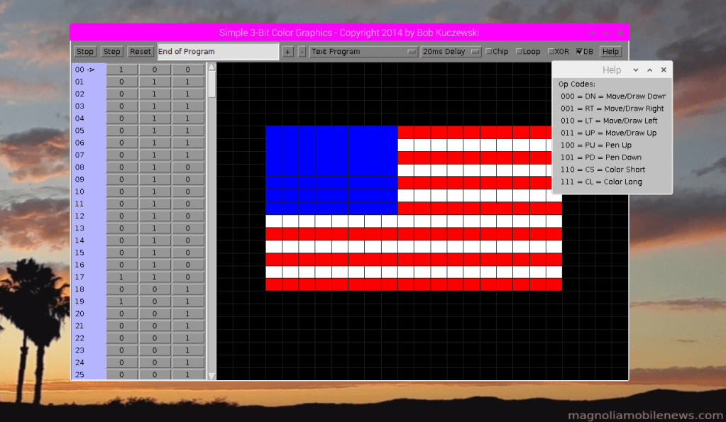
The following image shows part of the program to draw the U.S. Flag. The instructions shown are R, R, CS 111, D, L, L, L, L. The Color Short instruction (“CS”) is followed by the immediate data value of “111” which is the color code for white as needed to draw parts of this flag. The entire program uses multiple “Color Short” commands along with “Pen Up” and “Pen Down” commands to draw the red, white, and blue parts of the flag:

The same exact computer can run a different program to draw a different image. In this next example, the computer program draws a “smiley face” in color. This little computer can be used to draw almost any image that uses the 512 colors available. It’s just a matter of writing the proper program.

Conclusion
This series of simple “machines” starts from the simplest mechanical computer and progresses to a graphical computer capable of drawing almost any image using hundreds of colors. These computers all have well-defined binary instructions which could also be represented by more human-friendly operation codes. The human programmer would typically write their program using op codes, and another computer program (“assembler” or “compiler”) would translate those op codes into the binary machine code that can be understood by the computer itself. This is the fundamental process used in writing all kinds of computer programs. Of course, modern computers are much more complicated, and the instructions are much more complicated, but the overall process is very similar.
You can find JavaScript versions of some of these computers here:
